Kimball Physics UHV (Ultra-high Vacuum) Multi-CF Vacuum Chambers are precise, modular, multi-port fittings and housings that utilize integrated ConflatTM (CF) sealing surfaces at each port. We refer to them as MCFTM or Multi-CFTM vacuum chambers or fittings and they are available in several sizes and configurations. These compact designs are generally compatible with most other vacuum fittings in the industry with the bottom line of facilitating the efficient creation of clean reliable vacuum environments.
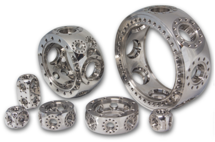
Figure 1. A small representative selection of Kimball Physics MCFTM chambers including Spherical Octagon, Square, Hexagon, Triangle, and Single and Double Spherical Cube geometries demonstrating the range of features and sizes available
Kimball Physics’ Multi-CFTM UHV fittings are designed as both instrument housings and as vacuum chambers, with the specific design intent to 1) conveniently support a diversity of internal apparatus, 2) permit complex port arrangements, 3) maximize interior functional volume while remaining compact to minimize their external footprint, 4) provide convenient internal access, 5) improve pumping efficiency, 6) follow a modular dimensioning system and 7) cluster together in close proximity.
In addition, the devices maintain compatibility with the existing fittings and accessories available from most manufacturers. The efficient and compact design enables improved instrument performance, lighter systems, better structural rigidity, smaller pumping systems, easier portability, and almost always lower total cost.
With a paradigm shift in the design and manufacturing of UHV vacuum structures, Kimball Physics brings innovation, precision and quality to vacuum chambers and housings for your research, applications, and advanced technologies.
The overall shape of the chamber housing is generally based on a hollow spherical geometry, with the outer surface, excluding the ports, convex and with the inner surface generally concave (Figure 2).
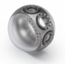
Figure 2. Spherical Octagon Multi-CFTM chamber with hollow sphere overlay to illustrate the underlying spherical structure of the design
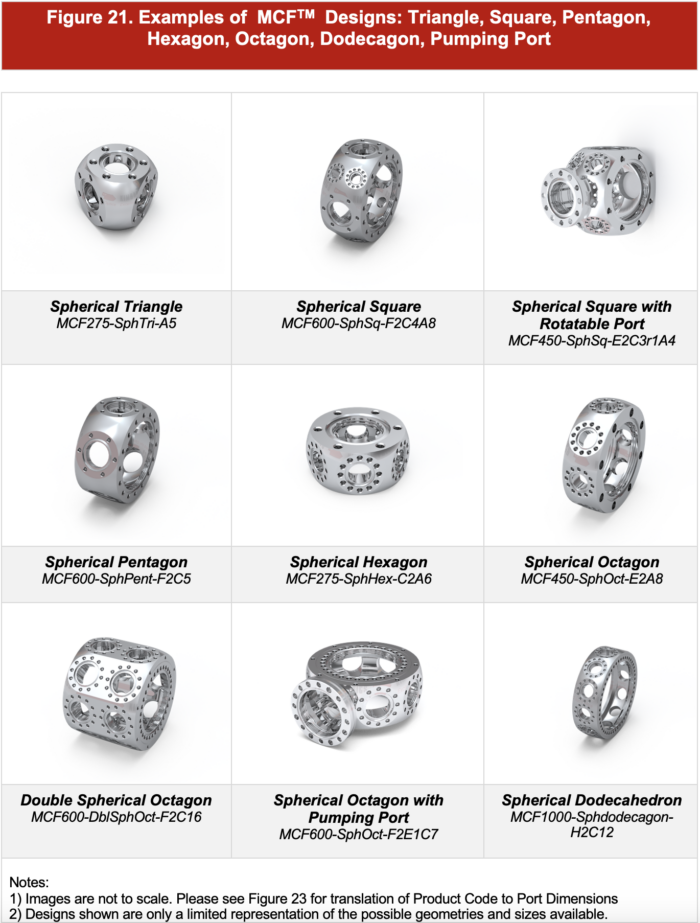
The vacuum chamber design is initially based on an internal and external spherical geometry. Many configurations are available to provide numerous options for your specific application, including our most common product designs of Spherical Cubes, Spherical Squares, and Spherical Octagons. Other versatile designs are also available for your application: Spherical Decagon, Spherical Dodecagon, Spherical Hexadecagon, Spherical Hexagon, Spherical Pentagon, and Spherical Triangle.
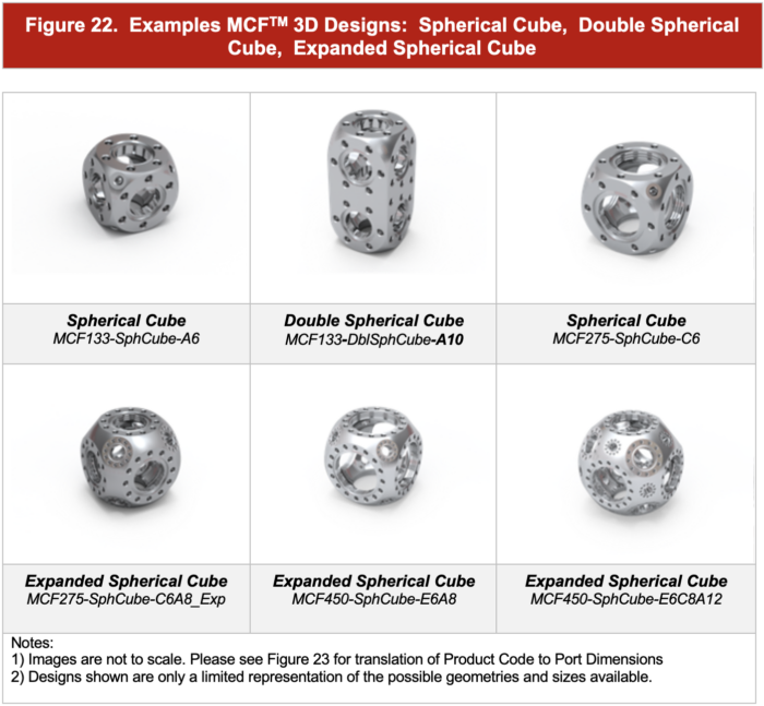
Also please refer to Figure 21 and Figure 22 below to see a sample of the various geometries and configurations.
The chamber sizes range from miniature and sub-miniature designs (with primary CF ports of 0.95″, 1.33″ and 2.75″) up to systems with 4.50″, 6.00″, 8.00″ and 10.00″ primary ports.
The chambers are typically fabricated from a single piece or monolith of 316L Stainless Steel. Custom designs are also available in Titanium for reduced weight, low magnetic permeability, and minimized outgassing of hydrogen for Extreme High Vacuum (XHV) applications.
The next level of structure in the chamber design incorporates various geometric configurations to provide a wide array of options for your system design. For example, the ports can be arranged in various planer geometries such as triangles, squares, pentagons, hexagons, octagons, dodecagons and three-dimensional configurations such as cubes (Figures 1, 21, 22).
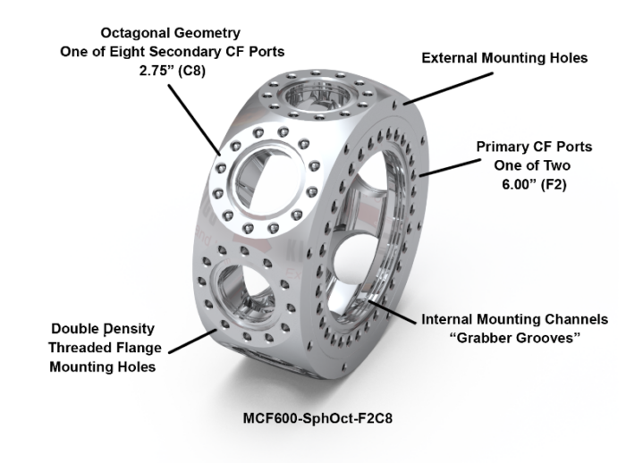
Figure 3. Spherical Octagon demonstrating planer octagonal geometry with annotations highlighting double density threaded flange holes, grabber grooves (internal mounting channels), and external mounting holes.
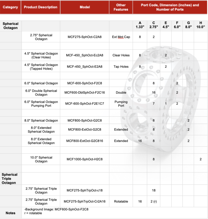
As an example, a 6.00” Spherical Multi-CFTM Octagon vacuum chamber (MCF600-SphOct-F2C8) has two large primary 6.0” (F) CF sealing ports that are symmetrically and concentrically placed. (Please see Figure 3)
In the planer section, a series of 8 2.75” (C) CF ports are perpendicular to the plane and equally spaced to provide an octagonal geometry of CF sealing ports. Overall, the vacuum chamber includes 10 ports.
Of course, there are exceptions to this general form with numerous other design variations, and where space is available, additional smaller ports that have and can be added. We often joke that the diversity of designs is the result of physicists running amuck with advanced CAD software and CNC machines. With kidding aside, the innovation in these designs emerged from a necessity for parts that simply didn’t exist. The results have led to an innovative and strategic series of UHV hardware components for chambers, housings and in-vacuum apparatus.
The Multi-CFTM structure has minimal internal welds, smooth contoured surfaces, and highly polished surfaces to provide optimal conditions for ultra-high (UHV) and with the titanium option, extreme high (XHV) vacuum conditions.
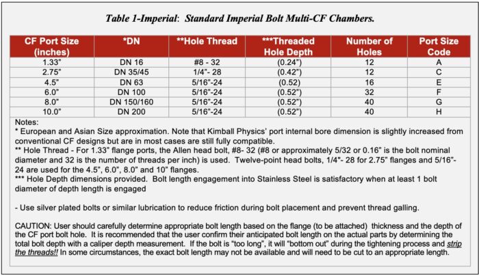
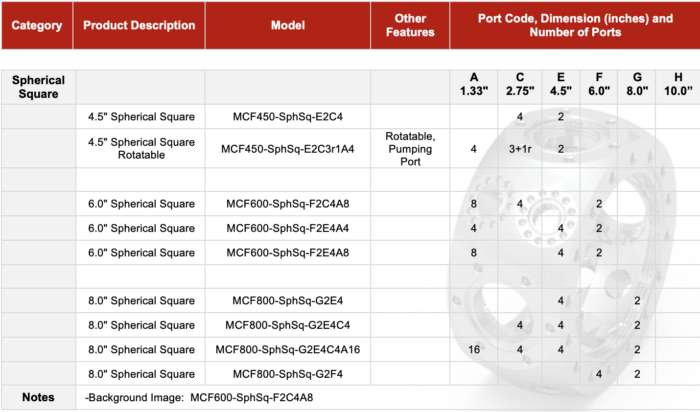
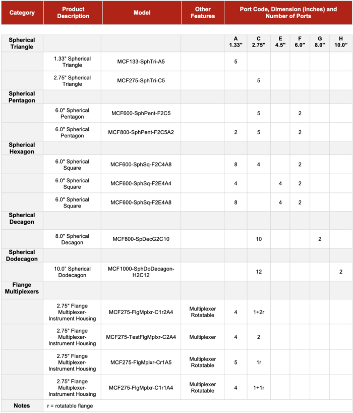
The CF sealing ports are available in standard sizes with diameters and letter designation codes of 1.33”(A), 2.75”(C), 4.5”(E), 6”(F), 8”(G) and 10”(H). (see Table 1)
The Multi-CFTM chambers are typically fabricated from a monolithic or single piece of 316L stainless steel with the CF sealing surfaces directly machined into this main or primary structure.
This design approach optimizes 1) weight to structure (with high stiffness and resonant frequency), 2) the functional internal volume with minimized internal surface area and outgassing in high vacuum experiments, and 3) reduced external dimension for a given functional internal volume.
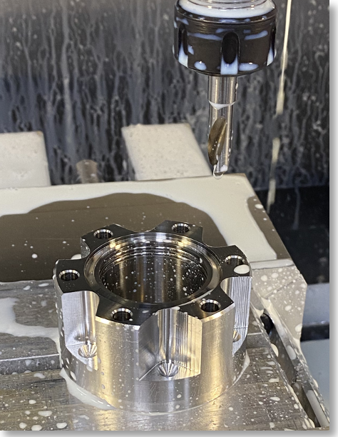
Figure 4. CNC fabrication in progress of flange features, with CF flange recess, knife edge, internal “grabber groove” channels being fabricated.
This efficient use of volume minimizes unusable internal space and allows more efficient pumping while also minimizing the components external dimension footprint.
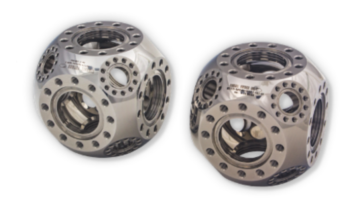
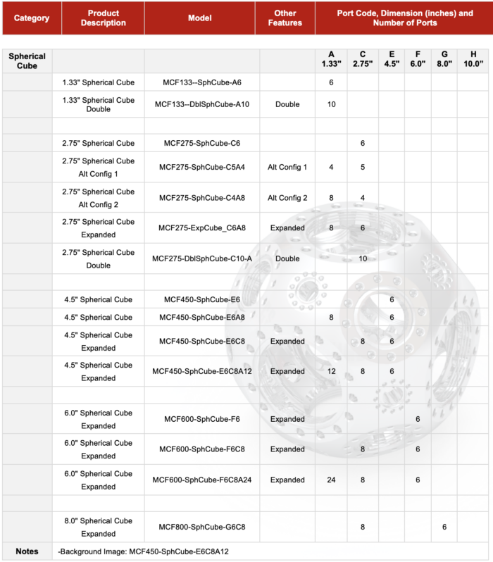
Figure 5. Spherical Cube Multi-CFTM Stainless Steel 316L (left) and Titanium Alloy (right) Spherical Cube UHV Vacuum Chambers with six (6) 2.75” (C) ports and eight (8) 1.33”(A) additional ports.
Custom chambers of similar configurations can also be fabricated from various grades of titanium (Figure 5). Titanium chambers, although more expensive, add additional benefits including very low magnetic permeability and minimized outgassing of hydrogen when pumping to extreme vacuum (XHV) levels. With titanium about half the density of stainless steel and similar in structural properties, the systems are also significantly reduced in weight.
As previously noted, these monolithic structures are fabricated from a single piece of metal stock using advanced CNC technology. This fabrication approach allows for the efficient use of material volume and structure in these configurations when compared to other structures in the industry that are typically fabricated from multiple component pieces that have been welded together. A high level of precision is possible with these manufacturing techniques, with port alignment typically within 0.1 degrees.
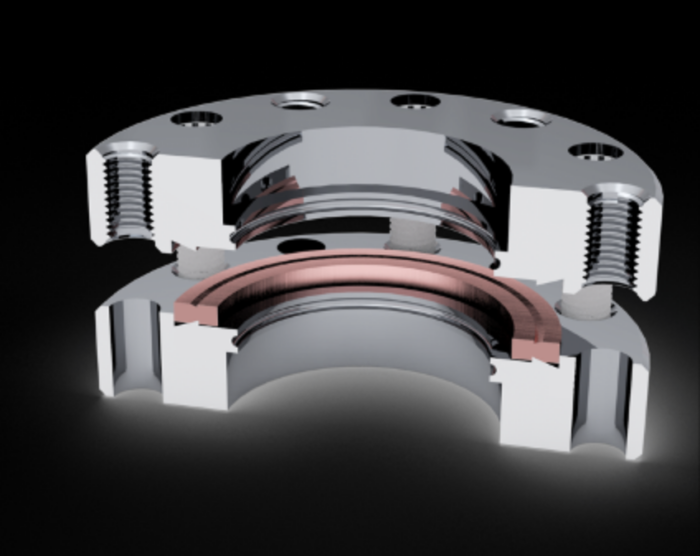
Figure 6. Schematic section view of CF flanges that were initially engaged and then separated to illustrate the sealing surfaces and the sealing groove created in the malleable copper gasket by the knife edges in the recess of the CF flanges.
The ConFlat® flange (CF) sealing surfaces are machined directly into the global structure. This sealing surface, which utilizes a knife-edge geometry, is used with an interposed malleable copper gasket and provides both a seal and a structural and stable connection between the flanges of various components. Predictable seals for ultra-high vacuums (UHV) and even extremely high vacuums (XHV) that accompany very low pressure (< 10-11 torr) applications can be reliably obtained over a broad range of temperatures.
The Multi-CFTM inside port diameters (bore diameter) in Kimball Physics components have been slightly enlarged from conventional designs to allow better access to the chamber’s internal volume and also increase conductance, allowing for more efficient vacuum pumping. These improved port features are still compatible with standard CF sealing surfaces while maintaining their structural and sealing integrity.
Other features of our vacuum chambers that optimize UHV and XHV applications include highly polished mirror-like surfaces, with smooth rounded contour surfaces to minimize internal surface area and with few or no welds within the vacuum space (any welds present are welded from the inner surface). Our distinctive appearance is well-known throughout the industry and attests to the highest levels of precision, quality and function.
A circumferential array of double density threaded holes is typically associated with the flange port of each CF sealing surface port when size allows (Figure 6). This enables the chambers to be clocked or rotated in smaller angular increments and also provides redundancy (e.g. if there is a problem with a bolt and it damages the thread).
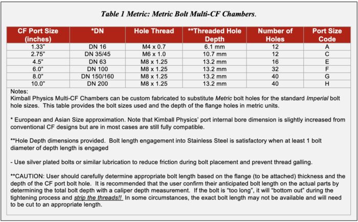
The holes are typically available with Standard thread (UNC, UNF- see Table 1 Imperial), but metric threads are also available on request (see Table 1 Metric). We recommend using silver plated bolts or similar lubrication to reduce friction during bolt placement and prevent thread galling.
Although there are twice as many holes, only half of the holes are typically used to secure the adjacent flange. These added holes also allow for the adjacent chambers to be mounted in similar orthogonal orientations when directly connected to each other using Kimball Physics’ Close Coupling Fittings. We discuss Close Couplers in more detail later in this document.
CAUTION: The user should carefully determine appropriate bolt length based on the flange (to be attached) thickness and the depth of the CF port bolt hole. It is recommended that the user confirm their anticipated bolt length on the actual parts by determining the total bolt depth with a caliper depth measurement. If the bolt is “too long”, it will “bottom out” during the tightening process and strip the threads!! In some circumstances, the exact bolt length may not be available and will need to be cut to an appropriate length. The recommended minimal bolt engagement in a bolt hole is one full diameter of the bolt. The ideal engagement is 1.5 to 2.o times the bolt diameter. This can vary and is also related to the materials comprising the bolt and the vacuum chamber bolt hole. The user should do their own research to confirm the best configuration for their application.
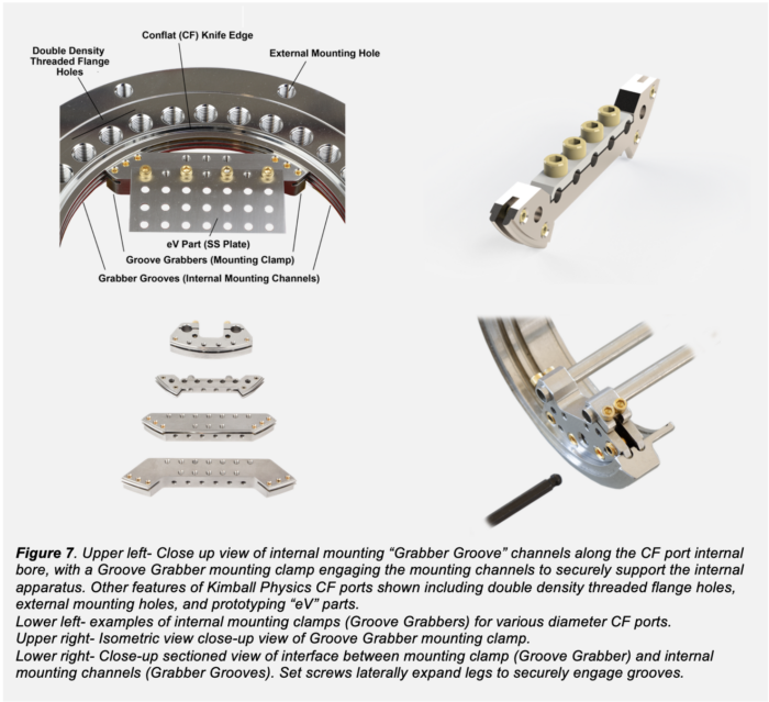
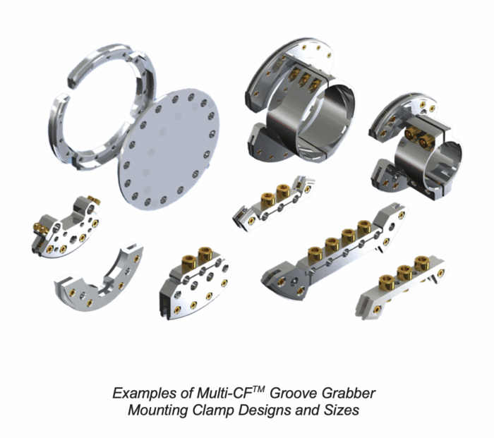
Internal circumferential channels, that we refer to as Grabber Grooves, are typically present along the inside bore of the CF aperture in ports with sealing surfaces greater or equal than 2.75” inches in diameter (Figure 7). The Grabber Grooves are used to securely attach (mount) various devices and apparatus to the inside of the chamber using Grove Grabber Mounting Clamps / connectors.
The Grabber Grooves typically have the same cross-sectional dimension in all flange diameters allowing for some interchange of Groove Grabber connectors as the port diameter allows.
Mounting flanges and flange adapters are also available that can be attached to other manufacturers’ CF fitting to provide grabber grooves and external mounting channels when there are no integrated mounting grooves available in the chamber structure (discussed later in this document).

To provide numerous options to mount your apparatus using the internal mounting channels or grabber grooves inside the MCF chamber housing, or to construct a custom prototype or functional device, we have a complete line of “eV Parts”, which are often referred to as a virtual “erector or play set“ for scientists (Figures 8, 9).
Kimball Physics eV Parts are a group of 350+ standardized parts, including ceramic and metal rods, perforated plates in various geometries, and a variety of fasteners and other parts that enable construction of all types of surface physics and high vacuum apparatus. These versatile parts are made from high quality materials to build rigid, self-supporting, self-aligning and dimensionally stable assemblies that allow accurate alignment of lenses, slits and apertures. They interface to our mounting connectors (groove grabbers) and also enable you to create custom prototype devices, or interfaces to your own devices and securely mount them inside the chambers. These eV parts save time and money by bypassing the need to design and custom machine these parts.
Please refer to our website for a more in depth discussion of the scope and capabilities of this product.
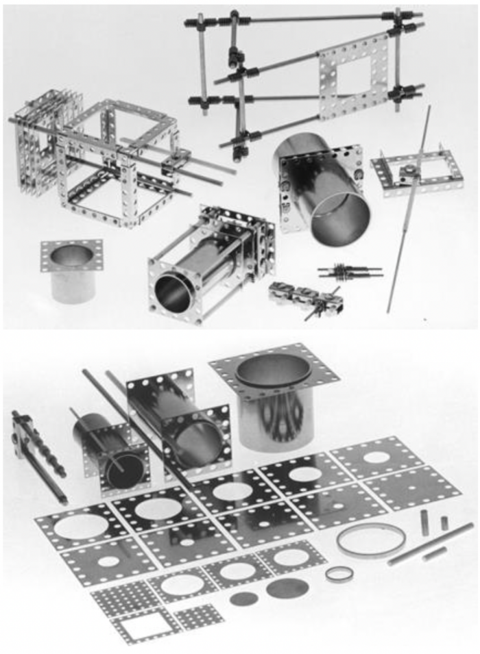
Figure 8. Assortment of various metallic and ceramic eV Parts available for mounting your apparatus or creating prototype devices.
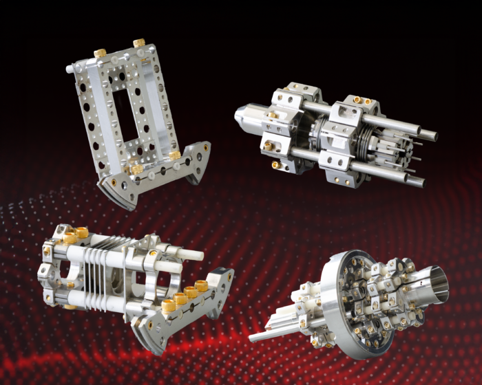
Figure 9. Examples of prototypes fabricated with eV parts.
ConFlatTM CF fitting vacuum chambers are frequently supported or mounted to an optical bench or apparatus by placing auxiliary mounting brackets under the bolt heads of the flange gasket compression bolts. Unfortunately, the varying loads on the brackets can cause non-unform loading on the bolts, which in turn causes variable loads on the gasket that may reduce seal uniformity and reliability.
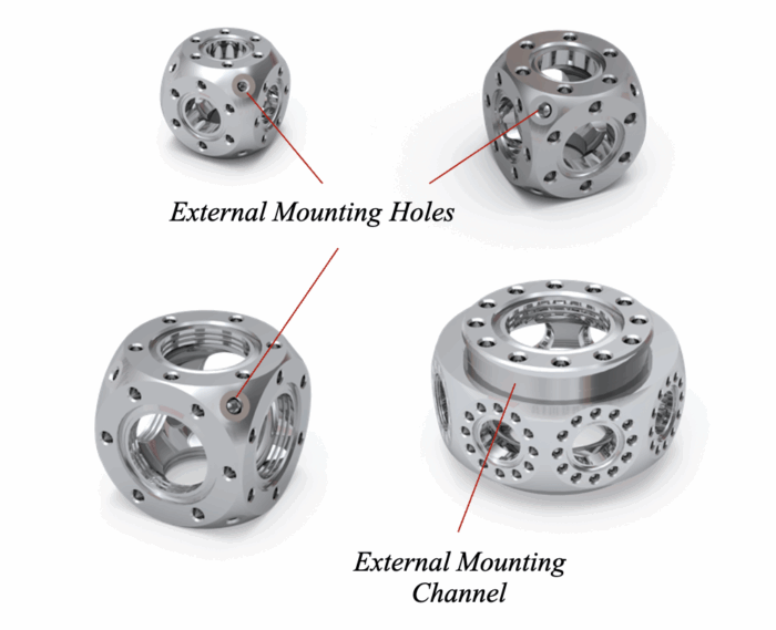
Kimball Physics has several alternatives to enable external mounting without compromising the CF gasket seal integrity. These include 1) additional threaded holes on the external surface of MCF chambers (Figure 7), 2) external channels on the MCF chambers to independently engage the mounting structures (Figure 10), or 3) mounting flanges with an outer diameter circumferential channel to engage mounting brackets (Figure 12).
When space is available, many of the MCF designs will have independently placed threaded anchorage points that are not involved in gasket compression. This provides an ideal solution for external mounting. Bakeout heaters can also be attached by means of these extra holes (Figure 7).
Also when space is available, externally placed channels can be integrated into the MCF surface and provide favorable structure for External Mounting Brackets without placing any loads on the sealing surface (Figure 10).
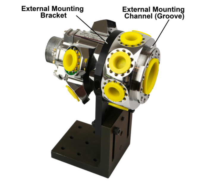
Figure 10. Spherical Octagon with bilateral mounting channels with External Mounting Bracket engaged. Temporary port covers are in place to protect CF surfaces including their knife-edges.
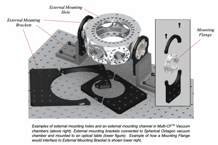
When the CF port sealing flanges are the only source for mounting, mounting flanges are available with circumferential channels that allow the external mounting bracket to engage the outer diameter of the flange while enabling access to the attachment bolts. The load to support the system is more evenly distributed to the entire circular flange, allowing the bolts to be uniformly tightened with more consistent compression of the flange knife-edge into the copper gasket sealing surface (Figure 12).
The original multiplexer design (unpatented) was developed at Kimball Physics in 1983. The objective was to allow many smaller ports to merge and be connected to a single larger port. This requirement is frequently encountered to accommodate the several feedthroughs that are needed to connect with the apparatus within the chamber.
Kimball Physics has several Flange Multiplexer designs. The Flange Multiplexer (MCF275-FlgMplxr-Cr1A5) is an evolution of our original design and includes five (5) 1.33” (A) CF ports which merge into a single rotatable 2.75” (C) CF port. The new design incorporates several new features, including: 1) a rigid unitary construction where only one weld (of previous eight) remains, 2) the inclusion of high strength Grabber Groove technology for internal mounting capability, 3) improved port alignment accuracy, and 4) better UHV cleanliness.
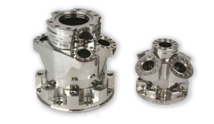
Figure 11. Flange multiplexers that provide additional ports that can be added to a single CF port.
Two sets of bolt holes are provided, one tapped and one clear, to allow the user to choose the mode of attachment of the base (the base may have either threaded or clear holes). The bolt ring is confined such that it cannot slide axially back from the sealing surface; thus the sealing surface is not exposed to damage (as is the case with ordinary rotatable flanges).
Flange Adapters are available to interface with CF fittings from Kimball Physics and other manufactures to provide 1) internal mounting capabilities (Grabber Grooves), 2) external mounting capabilities, 3) tilt of the port aperture, and 4) reduction in the port aperture diameter.
Flange Adaptors permit the Grabber Groove internal attachment system and external mounting channels to be added to ports of sizes 2.75”, 4.5”, 6.0”, 8.0” on systems from Kimball Physics and other manufacturers that utilize CF sealing surfaces. The grabber grooves provide versatile and stable means to mount hardware within the vacuum space. The flange adapter also provides an outside diameter channel that can be used for external mounting brackets (Figure 12).
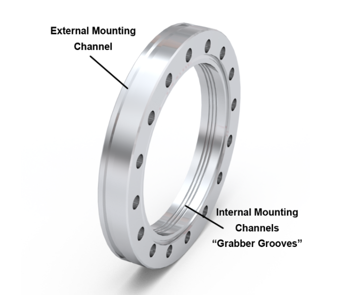
Figure 12. Flange adapter that interfaces to CF sealing surfaces to also provide additional internal and external mounting channels.
Tilt adapters are also available and were initially created for laser applications where it can be advantageous to have a viewport tilted off axis to avoid damage due to reflected beams. Angles of 2 and 4 degrees are available standard with custom angles up to 10 degrees available upon request.
Flange adapters are also available to reduce the port size diameter while providing both external and internal mounting features.
The Thin Flange is a new type of UHV CF flange designed for in-vacuum mounting to provide versatile solutions to standard ConflatTM CF ports (Figure 13). The Thin Flange can either have an open bore to 1) to bring grabber grooves to a port for in-vacuum mounting or to be used as a spacer, or 2) they can be solid and allow the flange to be custom machined to include various mounting holes or for a custom-sized apertures for various applications such as calibration of pumping speed, determining the outgassing rate of a chamber, differential pumping, and the ability to provide a platform for mounting experimental apparatus.
The Thin Flange also provides an easy method for inserting a phosphor screen RHEED screen or similar detector in front of a vacuum window.
Figure 13. Thin Flanges in various sizes, thickness, with open internal bores or solid plates.
The Thin Flange design has CF recesses with knife-edges on both sides to typically interface with the malleable copper gaskets. They can be inserted between two common CF style flanges from almost any manufacturer and are available in 1.33” CF, 2.75″ CF, 4.5” CF, 6.0” CF and 8.0” CF port sizes. Two thicknesses are available: 0.175 inch and 0.400 inch. The 0.400 inch open bore flanges include one pair of Grabber Grooves on sizes of 2.75” CF or larger. The thinner 0.175 inch flanges are not thick enough to include Grabber Grooves.
The existing system flange bases on either side of the Thin Flange provide the bending resistance necessary to have a uniform crushing force along the gasket perimeter, with even and symmetric forces on the interposed thin flange component when the bolts are
tightened. The gasket crushing bolts pass through the Thin Flange clear holes without putting any force on it. Thus, the Thin Flange does not experience any bending moments, and has no minimum required thickness to prevent bending.
Close Couplers are narrow two-port Multi-CF Fittings, consisting of a machined thick-wall cylinder, with opposing same-sized CF sealing surfaces (1.33”, 2.75”, or 4.5” for the non-rotatable couplers). The Close Coupler minimizes overall distance in joining two tapped hole flange components, resulting in the shortest possible distance between them (Figure 14).
The close coupler with non-rotatable flanges is based on the angular staggering of oppositely directed (180o reversed) bolts. By reducing the flange thickness under the bolt head while still maintaining adequate rigidity (based on the machined thick-walled cylinder), it possible to use slightly shorter bolts that can be placed into the coupler holes in alternating directions with access still available to tighten the bolts into the threaded flanges.
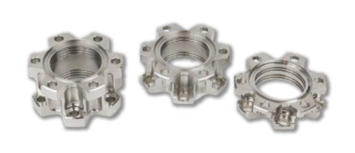
Figure 14. Close Couplers with various available spacing dimension to allow chambers to be joined in close proximity.
With this approach, the two CF structures can connect with a minimum interposed distance. If the structures being joined have a double density hole pattern, as found in our Kimball Physics 2.75”, 4.5”, 6.0”, 8.0” and 10.0” MCF ports, the angular orientation of the structures can be similar. We also include internal mounting “Grabber Grooves” in these structures.
If your application requires joining two structures that have the conventional hole pattern (not the double density pattern), the structures will be rotated with respect to each other one-half the angular spacing between the bolts in the pattern unless they have rotatable flanges.
If it is preferred that the two adjacent structures with conventional bolt patterns and with no rotatable flanges are to be joined in the same angular orientation, this can be accomplished with Kimball Physics Rotatable Close Coupler, which provides the ability to rotate one of the flange surfaces and allows for increased flexibility in placing the bolts, assembling fittings and in adjusting systems after assembly.
Perimeter Weld Flanges are weldable UHV CF flanges available at Kimball Physics. The flange contains the CF sealing surface with a circular double density tapped hole array. (Figure 15). The circular base is typically welded to spherical chamber’s surface to provide a prefabricated port sealing surface. However, they also may be welded to tubes, cones, ellipsoids, plates, and other shapes. By placing the weld lip on the outer perimeter of the flange, it is possible to significantly improve access to the interior of a system, while simultaneously reducing overall size. Each 2.5” or larger flange has one or more pair of internal mounting Grabber Grooves. They also include external outside diameter channels for external mounting capability.
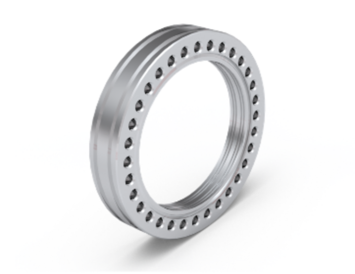
Figure 15. Perimeter Weld Flange which includes double density hole array and both internal and external mounting channels.
Weldable Clusters provide the option of attaching a multiple CF sealing surfaces to an instrument housing or vacuum chamber (Figure 16).
The structure is CNC machined from a unitary piece of 316L Stainless Steel and provides exceptional internal volume and access. The base consists of a 6” weldable port on the structure’s main axis that can be attached to a 6” tube or a 6” CF flange (with some preparation). The port transitions to a 4.5” port on the original axis and there are two options for additional ports, 1) two angled 2.75” CF ports or 2) four angled 2.75” CF ports. The 2.75” and 4” ports include double density holes and circumferential internal mounting channels (Grabber Grooves). These structures provide a versatile solution to add multiple port CF access to your instrument housing or vacuum structure.
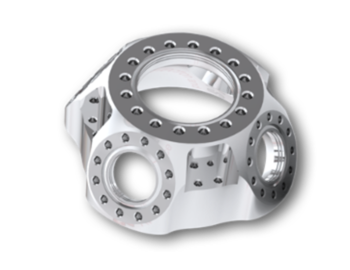
Figure 16. A Weldable Cluster with prefabricated CF sealing ports that can be welded to a system to provide compact multiport access.
Two way and four-way Flange Cross Fittings are a compact solution to provide multiple ports in a small region, in essence a miniature vacuum chamber (Figure 17). The fittings are CNC fabricated from a unitary 316L SS structure and are available with either 4 CF sealing ports (2- 2.75” and 2-1.33) or 6 CF ports (2- 2.75” and 4-1.33”). The 1.33” ports contain double density threaded bolt holes and all 2.75” ports include internal mounting channels or Grabber Grooves.
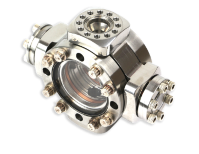
Figure 17. Example of a Compact Four Way Flange Cross fitting with mounted accessories including a viewing port and flange port covers in place.
Low friction Silver Plated Machine Bolts, with 12-point heads (12-point flange head cap screw), are typically used on ports of 2.75” and greater and allow wrenches with smaller head dimensions to be used in limited spaces to advance the bolt in smaller angular increments to torque the bolts (Figures 18 and 19).
It is essential that the correct bolt diameter, thread pitch and length are chosen to prevent the screw from unintentionally “bottoming out”. Low friction silver surface bolts are used to minimize the chance of the screw inappropriately binding (galling) or breaking.
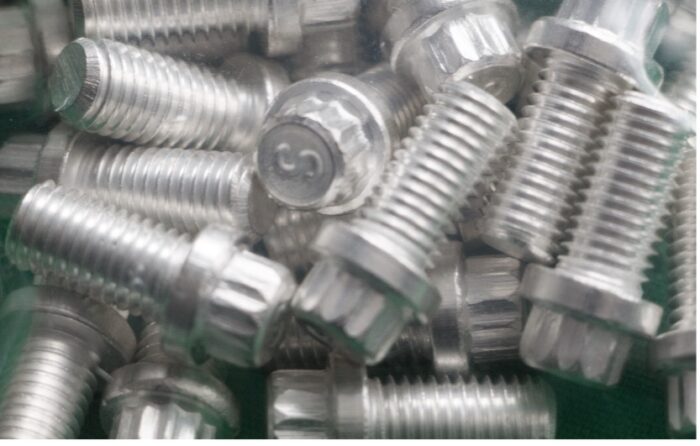
Figure 18. Low friction silver plated bolts with 12-point heads.
Three basic bolt sizes (diameters and thread pitches) are typically used with Kimball Physics’ vacuum hardware (Table 1). For 1.33” flange ports, the Allen (Hex Head Cap Screw) head bolt, #8- 32 (#8 or approximately 5/32 or 0.16” is the bolt nominal diameter with 32 threads per inch) is used. Twelve-point head bolts, 1/4″- 28 for 2.75” flanges and 5/16”-24 are used for the 4.5”, 6.0”, 8.0” and 10” flanges.
Silver plated bold lengths are available in various sizes from Kimball Physics and other manufacturers. It is important to carefully calculate the total bolt length required by first measuring the thickness of the flange(s) being attached to the sealing surface, and then adding the estimated depth of the bolt entering the threaded hole. As a first estimate, it is recommended that at least 1 bolt diameter in length engages the stainless steel threaded hole. The total depth of the flange holes are approximately two “bolt diameters”. Please refer to the specifications of the flanges for more detailed information and use a digital caliper to confirm the thickness dimensions of flanges, the depths of threaded holes, and bolt lengths.
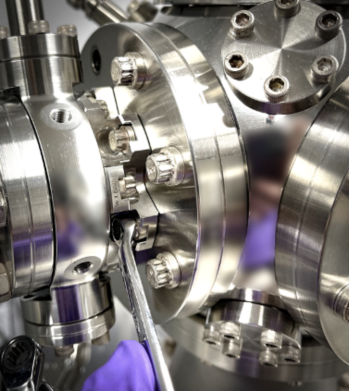
Figure 19. Silver plated bolts (#8-32, 1/4″-28 and 5/16”-24) used to secure flanges in a typical vacuum system. Allen hex heads with #8-32 bolts, and 12-point heads (1/4”-28, 5/16”-24) are present. Wrench in place to finish tightening 1/4”-28 bolt in limited space of a close coupler flange.
Please note that metric bolts, used for specially requested metric MCFTM systems, are not available with 12 point heads, whereby the user may encounter more limited tool access to the socket head cap screws on metric bolts, especially notable in Close Coupler fittings.
Malleable Copper Gaskets provide the sealing surface between the CF flanges of a vacuum system. Diametrically opposed knife-edges create a clean fresh groove into the gasket to provide a durable and high vacuum seal. (Figures 6, 20).
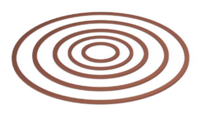
Figure 20. Nested copper gaskets for CF ports of 1.33”, 2.5”, 3.75, 4.5”, 6.0”, 8.0” and 10.0” are shown for size comparison of CF port apertures. The gasket thickness, 0.080” remains constant.
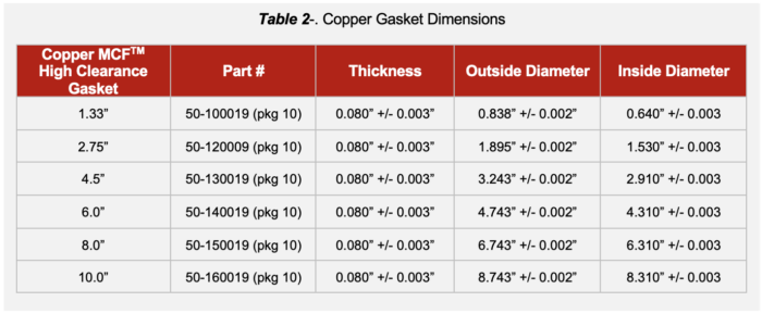
The copper surface is clean and free of contaminants and UHV compatible with high vacuum conditions over a broad temperature range. Table 2 gives an overview of the typical copper gasket dimensions that are used. Using Kimball Physics MCFTM vacuum chambers with expanded port internal diameter (ID) dimensions (for improved physical access and pumping conductance), “high clearance” gaskets that include a slightly expanded inside diameter (ID) dimension is recommended and available at Kimball Physics.
If you don’t see the Multi-CF TM(MCFTM ) vacuum chamber or housing that you need for your application, please reach out to Kimball Physics to engage our specialists if you may need a custom design for your specific application. A significant portion of our MCFTM chambers and instrument housings are designed and manufactured for the specific needs of our customers.
And although our MCFTM chambers and accessories come with Standard Imperial CF port dimensions and bolt threads, metric sizes are also available upon request.
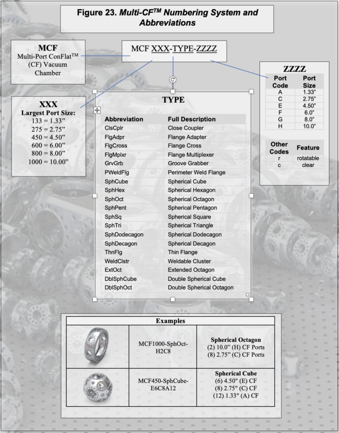
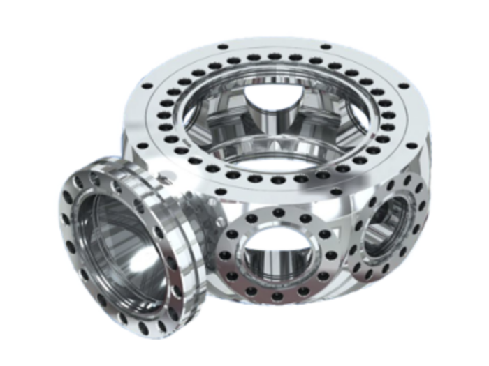
Figure 24. 6.0” MCFTM UHV Spherical Octagon with (2) 6.0” ports, (1) 4.5” high conductance welded, non-rotatable pumping port and additional (7) 2.75” ports. External mounting bracket capable with (8) threaded holes on each 6.0” flange face. Grabber grooves for internal mounting are present on all ports.
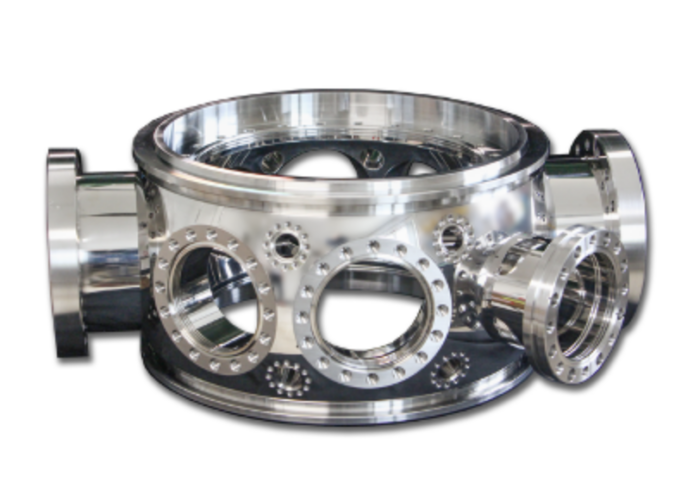
Figure 25. Custom 12” MCFTM Spherical Octagon vacuum chamber with 1) enlarged ports with increased conductance for better pumping efficiency and 2) offset port surfaces for specific design requirements.
For more information about Multi-CFTM (MCFTM) Multiport Vacuum Chambers and Accessories, visit our website at: Multi-CF Hardware
Vacuum Chamber Product Page direct links:
Multi-CF Hardware
Several of the design features in our MCFTM products are covered under Kimball Physics U.S. Patents: 5,593,123; 5,625,947; 5,660,418; 5,671,956; 6,270,945; 6,678,937; 7,216,899; 8,191,901; 8,695,987
For more information about the various materials used in vacuum chamber fabrication, their mechanical and magnetic properties, and various requirements for high and extremely high vacuum chambers and hydrogen diffusion, please refer to our Learning Center Topic: Materials and Magnetic Properties
Reference Document: MCF_Vacuum_Chambers_Overview_2023_0220
Copyright Kimball Physics 2025, ALL RIGHTS RESERVED