
Kimball Physics specializes in the design and manufacturing of precision high-tech scientific instruments with over 50 years of experience in ultra-high-vacuum electron and ion optics. Our expertise is in high stability electron emitters, precision electrostatic and magnetostatic optics, along with state-of-the-art vacuum chambers and fittings. Electron and ion systems are optimized for beam energies ranging from 1 eV to 100 keV and beam currents from femtoamperes to amperes.
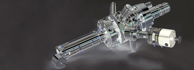
Figure 1. Example of a Kimball Physics Electron Gun.
Our goal with this informal resource is to provide a fundamental knowledge base for understanding the basic terminology, principles and parameters, and specifications of electron and ion beam systems.
Many scientists, engineers and graduate students would like to incorporate electron and ion beam systems into applications within their specific fields and need to “get up to speed” quickly with this fundamental information. With this information resource, our intent is to help you move more quickly towards your solution and to choose the electron or ion system and components that would work best for your application.
The first section, Introduction to Electron Beam Systems (101), is a ground level introduction to the terminology and basic mechanisms related to electron beam systems. The next section, Electron and Ion Gun Systems (201), provides more advanced details about the electron and ion beam parameters and the associated instrumentation. The intent of this section is to provide more specific and detailed information about the systems to enable the interpretation of the technical specification documents available for our electron and ion gun products and options. The last section includes basic Gun Operations and Questions. Advanced Topics (301) will be added over time and will dive into more detail about the scientific and technical aspects of chosen topics related to the systems.
Please excuse any errors or areas that are not complete; this document is always a work in progress!
Let’s get started with a dissection of an electron gun system with a basic discussion of how the various elements work and come together. For this first pass through the information, the description of each element will be basic. Later in the document, we will add more details, parameters, and technical description.
The figures included will provide an overview of a typical electron gun. The first figure above (Figure 1), is an exhibit of a typical electron gun. Figure 3 below is a simplified schematic of the electron gun components and applied voltages. Please reference these figures as we progress through the discussions that follow.
The electron gun is a descendant of the early vacuum tube, and some parts still utilize the same names although they are somewhat different in structure.
In a triode vacuum tube, which is the basis for many electron guns, there are three electrodes- 1) the cathode that generates free electrons, 2) the anode which attracts and accelerates the electrons to a displaced point in the beam direction, and 3) a grid (in electron guns know as a Wehnelt grid) to provide control of the electron emission from the cathode.
The simplest source of the electrons in an electron gun cathode could be a metallic wire or filament such as tungsten bent into a hairpin shape, where we apply a small voltage to pass a current through the wire’s resistance to heat the wire.
Depending on the temperature and characteristics of the wire, such as its work function (we talk more about work function, cathode materials, designs, and parameters in our cathode tutorial document), some of the electrons in the wire will have enough energy to escape their outer valance shells, become free electrons and then possibly emerge to the surface of the cathode and into the partial vacuum space just surrounding it (thermionic emission). The electrons initially exit from the material surface in several random directions and at low energies.
Electrodes are simply conductors with geometries that interface with non-conductors in the system (such as the partial vacuum space). They are typically used to establish a point of voltage potential and in this case, to create electric field gradients within the electron gun’s physical configuration. In addition to the cathode, the anode and Wehnelt grid, there are typically several additional electrodes present in the system that modify the path of the electron beam.
To facilitate the extraction of electrons emitted from the cathode, and then organize and accelerate them into a beam with more uniform characteristics, a strong primary electric field is created in the region.
The electron source or cathode (the negative electrode) is typically held at a large negative potential (such as -1000 V or more) with respect to the anode (the positive electrode), where the anode is in a position at some distance and in the intended beam direction. The anode could be in the shape of a conductive disk (if it was to be the target) or ring geometry if the beam was to pass through or by it.
The anode’s potential is often held at ground (0 V), which is at a much higher potential than the cathode’s negative potential. As the electrons are emitted from the source and accelerated towards the anode by the electric field established between the cathode and anode, they become somewhat more organized into a beam like structure. As the beam continues past the anode, other electron optics techniques and mechanisms are implemented to focus and modify the beam trajectory and other beam characteristics. The potential difference between the cathode and anode largely determines the overall energy of the electron beam.
The Schottky effect or field enhanced thermionic emission is a phenomenon related to how the electric field magnitude lowers the surface barrier for electron emission and allows increased emission current at a given temperature.
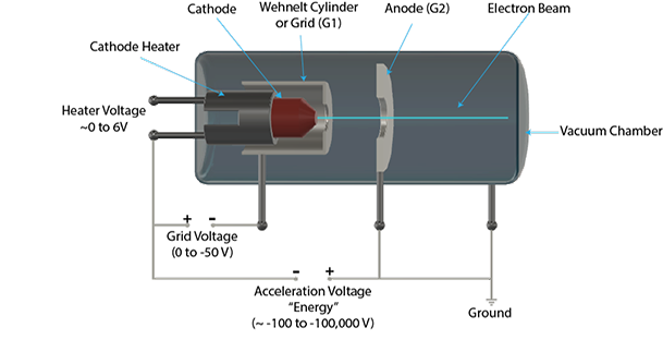
Figure 3. Schematic view of simplified electron gun with labelled components.
To help focus and control the release of electrons from the emitting source, a cup-shaped-cylindrical element with a hole or aperture in its center is placed in close proximity to the cathode (emitting) surface. This is commonly referred to as the Wehnelt cylinder or grid, and it is typically kept at a potential that is even more negative than the adjacent cathode source.
The potential difference between the cathode electron source and the Wehnelt cylinder creates another, more localized electric field, which is somewhat opposite in direction when compared to the primary electric field between the cathode electron source and the more distant anode.
At low magnitude, this electric field will suppress emission from the lateral surfaces of the electron source to initially help focus the random electrons into a more beam-like configuration. The electric field (formed between the cathode and Wehnelt) can also be increased to fully suppress emission of electrons from the electron source and can be used to create a pulsed electron beam. The Wehnelt or grid is the first element in a typical series of devices to control the electron beam that has been formed.
An interesting property of a glass lens is its ability to bend electromagnetic radiation. One typical application would be to focus light. Although an electron is considered to be a particle, it also has properties of a wave that can be bent and focused in a manner similar to electromagnetic radiation.
Lens for electrons are not made of glass, but rather use electrical conductors with voltages and currents to create electric and magnetic fields. Some of the ways an electron beam can be controlled include focus, zoom, deflection and rastering.
For example, wire can be coiled into a circular arrangement, and with current flowing through the wire core, a magnetic field is created that will focus divergent electrons that pass through it into a more collimated beam.
Conductive plates, diametrically opposed across the electron beam path with a potential difference between them creates electric fields that deflects the beam trajectory in a controlled manner.
A typical electron microscope lens system would be composed of a series of many electron optic devices that create both magnetic and electric fields across the electron beam path. As you can imagine, several challenges are present in these systems to optimize the beam alignment and other properties.
For example, the source of the electrons is not always aligned to the “longitudinal optical axis” of the system. Furthermore, the electron travel may not be parallel to the long axis of the system. To solve this problem, most systems incorporate magnetic deflectors to center and align the incoming electron beam. Additional magnetic coils, often referred to as stigmators, are used to help correct for asymmetries in the system. Finally, apertures are placed along the optical axis to block any electrons that are not aligned close enough to the intended beam axis.
Typically, all materials used in constructing the electron and ion guns are compatible with ultra-high vacuum (UHV) technology, which typically utilize pressures even lower than about 10-10 torr. It is important that any materials used in vacuum be UHV-compatible and not out-gas (release molecules when put into ultra-high vacuum).

Table 1. Examples of vacuum ranges and values. Data adapted from https://en.wikipedia.org/wiki/Vacuum
In addition, internal surfaces are typically smooth to not retain but rather facilitate evacuation of atmospheric gases and water vapor, with this material also non-volatile and non-porous to minimize leaching of gases. Materials that are bakeable (i.e., heated to 150 – 350°C) help to further liberate gases and enhance/enable high vacuum.
To enable these high vacuum conditions, the gaskets used between connected vacuum flanges need to have low or no volatility and tolerate elevated temperatures. Viton (a synthetic fluorocarbon polymer) or copper are typically used. A ConFlat™ flange (CF) system will typically use a cooper gasket ring that is positioned between the round flange surfaces of adjacent components, with each of those flange surfaces also including a circular concentric knife-edge. As the bolts between the flanges are tightened, the knife-edge deforms the copper surfaces to create a seal on both sides of the copper ring.
Feedthrough insulators are made of ceramic. In general, common materials (such as most types of insulated wire, rubber tubing, electrical tape, tape labels, duct tape or anything with adhesive) are not UHV vacuum compatible and must be avoided.
A partial list of UHV compatibly materials with very low outgassing rates (torr liter/sec cm2) for electron gun components include 1) metals; aluminum and alloys (6061, 2024), titanium, copper (OFHC), silver, stainless steel (304, 316), and tungsten, and 2) ceramics; glazed ceramics such as porcelain, and glasses such as Pyrex.
Other considerations in the design of UHV chambers include highly polished surfaces, minimally contoured interiors, and minimal welds, with geometry optimized for maximum internal access and a usable volume with minimal optimized surface area that allows a high density of experimental apparatus.
Kimball Physics has a product line of vacuum chambers with multiport CF interfaces that are fabricated with precision geometries and generally milled from monolithic pieces of either 316L stainless steel or various grades of titanium. Both the internal and external surfaces are highly polished. This system includes standardized CF mounting interfaces and incorporates mounting features: 1) external channels and bolt holes for supporting the system and various attachments, and 2) internal grooves circumferentially at most inner port diameters for supporting and positioning the experimental components. Kimball Physics also has a complete line of eV parts, essentially a collection of UHV compatible metal and ceramic parts (an “erector set” for scientists) that can provide structure and connectors to create and allow stable and precision support of systems placed within the vacuum chambers.
The quality of the vacuum affects the performance of the electron gun. To create an optimal electron beam, we need to get the air and water gas molecules out of the way.
Typical vacuum for electron beams is in the range of 10-6 to 10-7 torr (for reference, 1 atmosphere of pressure is ~760 torr). For ultra-high vacuum (UHV) applications, at least 10-9 torr is needed. Table 1 provides a nice comparison of the molecules in a cubic volume (cm3) and the mean free path (the average distance traveled by a moving particle between successive impacts or collisions) at atmospheric pressure and different levels of vacuum at room temperature.
The high vacuum (or similarly low pressure) is usually achieved using two types of vacuum pumps: a rough pump and a turbo-molecular pump.
An ion gauge, which is a miniature ion gun and detector system in itself, is used to measure the gas molecules present in the vacuum chamber and monitor the chamber pressure. The ion gauge is typically positioned in the vacuum chamber near the electron gun, but out of the way of the electron beam and target.
It is essential to establish a stable vacuum. An electron gun with a standard refractory metal cathode requires a vacuum of 10-5 torr or better, while a gun with a BaO (barium oxide) or a LaB6 (lanthanum hexaboride) cathode requires 10-7 torr. With some materials, such as Y2O3 (Yttria coated Iridium) cathode, a lower vacuum of only 10-4 torr is acceptable.
A poor vacuum can damage the cathode or reduce its lifetime. For example, the presence of oxygen or water vapor while the refractory metal cathode is hot (over 700 K) will cause oxidation of the metals, while at higher temperatures (over 1200 K) nitrogen will further degrade the cathode. Thus, the vacuum must be well established before the gun is turned on, and after the gun is turned off, the cathode must be allowed to cool down (usually for at least a half hour) before the vacuum system is vented.
If the electron gun is energized without a proper vacuum, it can be damaged by arc-overs. Maintaining a suitable vacuum state also keeps the cathode electron source surface from oxidizing and altering its emitting characteristics.
Power supplies at Kimball Physics typically feature a modular design with miniaturized power supply clusters, optically isolated signals, and a digital interface controller. A LabVIEW™ software virtual control interface is optionally available for many of the systems. Beam stability is an important requirement with stable energy and emission current controls from the power supply required to achieve this.
Figure 4 provides a schematic block diagram of the power supplies (represented as circles) that apply voltages to the parts of the gun to produce and control the electron beam in this one electron gun example.
The power supply provides multiple voltage and/or current sources to the various elements of the electron gun system. For example, a separate power supply module provides for Beam Energy, Source (ECC-Emission Control Current), Grid (Wehnelt), 1st Anode, Focus and X and Y deflection are present.
Typical ranges for each component power supply requirements are shown in the table below the schematic (figure 4).
Monitoring the output of the electron gun is typically used during initial gun operation to position the spot, or align the gun, and to determine various power supply settings for optimum performance. The electron beam can be visually monitored by observing the resultant spot on a phosphor screen or can be electrically monitored by measuring the beam current at the target (Faraday cup). The most desirable arrangement is to have both visual and electrical monitoring of the electron beam.
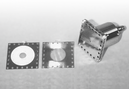
Figure 5. Faraday cup with optional phosphor screen.
Some of the possible monitoring choices include:
This section will provide more content about the electron/ion beam and its associated systems to enable the reader to better understand the technical details provided in the technical documents and specifications available for the various electron gun systems.
Typical ranges for electron beam energies span several orders of magnitude from 1 eV to 100 keV (100,000 eV). One of the most important characteristics of the beam is the kinetic energy of the electrons or ions. The electron beam energy is determined by the overall potential difference and distance between the cathode and anode that accelerates the electrons as they travel from the cathode source to the final aperture of the electron gun. This energy, measured in electron volts (eV or keV) and is controlled by the “Energy” power supply channel and can range from 1 eV to 100 keV depending on the gun. One eV is approximately 1.602 x 10⁻¹⁹ joules and is typically the amount of energy 1 electron acquires by accelerating from rest through a potential difference of about 1 volt.
The First Anode (G-2), the first of possibly multiple anodes in the beam path, is referenced several hundred to thousands of volts more positive than the cathode. The electric field created by the potential difference between the cathode and the anode also influences the degree of electron extraction from the cathode. This effect is modified by the electric field present between the Wehnelt or grid and the cathode, which can also modify the number of electrons emitted from the cathode.
The energy spread of the beam is a measure of the variation in energies (typically less than half an eV), as not all particles will exit with the same kinetic energy. The energy spread can vary with different cathode sources. For example, with a 100 keV system, the energy spread for a tantalum (Ta) cathode is ~0.5 eV, Yttrium oxide cathode (Y2O3) is ~0.4 eV, and Lanthanum Hexaboride (LaB6) cathode is ~0.4 eV.
Where the electron goes once emitted largely depends on its energy and the electrical fields in the space around the cathode. If the electron does not have enough energy, or if the space around it has too much negative charge (space-charge limited), the electron will return to the cathode. The electrons that do leave the cathode can be focused and accelerated into the electron beam.
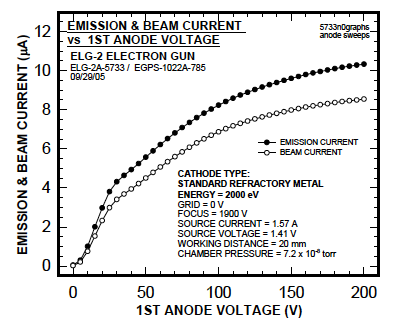
Figure 6. The effect of the 1st Anode Voltage on Emission Current from the cathode and the final Beam current
The emission current is all the electron current that leaves the cathode and eventually goes to ground. This emission current depends on both the cathode temperature and the electron beam energy set by the Energy power supply channel (approximately the potential difference between cathode and anode). However, not all the electrons emitted from the cathode will be in the electron beam that finally exits the gun (this can be measured by a Faraday cup at the end of the gun).
Some of the electrons may land on other elements in the gun column and return to ground, but not through the electron beam. Thus, the final electron beam current at the target will be less than the initial emission current.
As shown in electron gun example Figure 6, increasing first anode voltage increases the emission current, and thus increases the final beam current for a given set of operating parameters. This effect levels off at higher anode values, reflecting the change from a space charge limited situation to a temperature limited one. The first anode potential does not determine the final energy of the electrons, which is reached in this example, only at the grounded second anode after passing through the focus region.
The Wehnelt or grid voltage (G-1) will also affect the beam current. Increasing the Wehnelt potential makes the Wehnelt aperture more negative with respect to the cathode. As the Wehnelt potential increases (becomes more negative, also called increasing the grid bias), the electric field between the cathode and Wehnelt suppresses electron emission from the cathode perimeter, leaving only the center of the cathode to emit. If enough Wehnelt potential is applied, the beam will be completely suppressed, and the beam is said to be cut off.
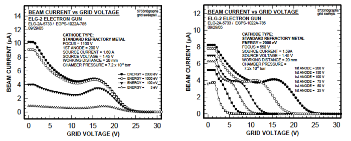
Figure 7. The effect of Grid Voltage on final Beam Current, showing cutoff at different Energy levels on the left, and showing cutoff at different 1st Anode voltages on the right.
This cut-off effect of increasing grid voltage is illustrated in Figure 7 at different Energy levels. Although Energy level affects the amount of beam current, it does not affect the cut-off point on this example system. The figure also shows the effect of different first anode (G-2) levels on beam suppression by the grid (G-1); the grid cutoff value is an increasing function of anode voltage.
Grid cut-off can be used to pulse the electron beam off and on. The various ways that pulsing can be accomplished using the grid are described in the pulsing sections below.
The electric field created by the Wehnelt also controls beam divergence and uniformity by varying electron trajectory.
The spot size is the diameter (cm, mm or µm) of the electron/ion beam at a given distance from the gun (working distance). This may range from a few microns to several hundred millimeters, depending on the gun.
The spot is measured either visually on a phosphor screen, or by a Faraday cup array; as the edge of the circle may not be clear cut, the full-width- half-max measurement (FWHM) is defined as the width that includes all beam current densities greater than half the maximum density.
In a flood gun, which does not have focusing lenses, the size of the spot is mainly dependent on the working distance, or how far away the target is from the end of the gun, although other operating parameters can also effect spot size.
In setting up the system, the working distance (the distance from the end of the electron gun to the target) will need to be determined. Many of the gun specifications are affected by the working distance; for example, at a longer working distance, there is more effect of noise, and beam current may be less, or the spot size may be larger. In general, the minimum working distance possible for the experiment should be chosen to reduce problems associated with transport of electrons, including space charge spreading of the beam and beam distortions from stray magnetic fields and stray electric fields (i.e., the Earth’s magnetic field and insulator charge-up).
Beam divergence is the angular spread of the electron/ion beam from the final aperture of the gun (in degrees) at the working distance and ultimately affects the spot size.
Beam uniformity describes the distribution of beam current within the spot. The beam current can be further characterized by measuring the beam current density- the beam current per unit area at the target (typically in µA/cm2).
The variation of beam current density at different positions within the spot is called the beam current distribution. In most guns, this is a Gaussian distribution; the spot is brightest in the central area and fades off at the edges. Other electron guns have electron optics elements designed to produce a flatter, more uniform electron distribution across the entire spot.
Brightness or source brightness is generally the electron density or number of electrons per unit area or (spherical sector) or is commonly defined as the ratio between the beam current and the beam emittance. Emittance is a property of a charged particle beam and is a measure of the average spread of particle coordinates in position and momentum phase space, typically with dimensions of length or length times angle. Increasing brightness is often achieved by increasing beam current with reduction in transverse emittance.
High brightness applications (which require small spot and high resolution) include scanning electron microscopes, transmission microscopes, electron probes, scanning Auger systems and electron lithography systems.
Below we continue our discussion about the electron optics elements that modify the transverse motion and axial velocity of the electron beam particles. The electron has an electrostatic charge and therefore its path can be deflected by an electric field. Furthermore, the electrons in the beam are moving, similar to the current in a wire, whereby there is a magnetic field associated with the beam and therefore it can be deflected by an applied magnetic field. The particles typically have minimal velocities perpendicular to their primary direction of motion. Thus, both electrostatic and magnetostatic fields can both be used to provide forces to change the properties and path of the electron beam. This includes beam focusing, zoom, deflection, rastering, stigmators and condensers. Another interesting property of the electron is that they will release energy as they change direction (i.e., release of photons in a free-electron laser).
Focus controls the diameter of the electron beam as it approaches the grounded aperture at the end of the gun. In a focusable gun, additional elements are present in the gun to further control the size of the beam.
One focusing approach consists of three axillary aligned cylinders which together form an electrostatic converging lens called an Einzel or single lens. The outer two cylinders are typically grounded while the middle cylinder is held at a fixed voltage (Focus Power supply). The electrostatic field is symmetric (see Figure 8) so that it the particles will regain their initial energy on exiting the lens although the direction of the outer particles will be changed such that they converge on the axis.
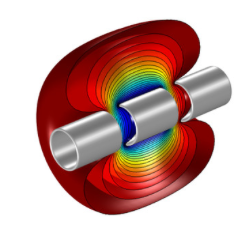
Figure 8. Computer model of the electrostatic field of an Einzel Lens for focusing charged particles. https://www.comsol.com/model/einzel-lens-14405
Some guns will have more complex lens systems, such as the zoom lens (see below), for focusing and accelerating or decelerating the electrons. The focus element is controlled by a voltage source referenced to the negative energy supply, typically in the range of 0 to 2 kV. Increasing the focus potential makes the focus element more positive with respect to the cathode. Focus, in conjunction with potentials on the other elements, affects spot size and forms part of the zoom lens. Focus controls the diameter of the electron beam as it approaches the grounded aperture at the end of the gun.
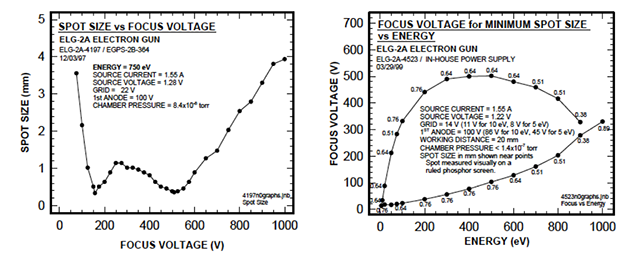
Figure 9. The effects of focus on spot size at a particular energy, showing two minimums (left), and The Lens Operating Curve, with the focus values required to produce the minimum spot size (right).
The Zoom Lens consists of the electric fields created by the potentials on first anode elements, focus and the grounded aperture components prior to deflection (please see figures 2 and 4 above). The beam is pre-accelerated in the first anode section and then focused and accelerated or decelerated in the zoom lens section. The beam attains its final kinetic energy at the grounded aperture, the second anode, which completes the zoom lens.
The zoom lens allows flexibility of control because the ratio between the voltages of each element can be varied; in addition, there can be less aberration with more lens elements. Beam energy, beam current, and beam divergence are all directly controllable.
The ratio of Focus voltage to 1st Anode voltage roughly determines the spot size, while the ratio of Energy to 1st Anode voltages determines the amount of acceleration or deceleration that the electron beam undergoes. Since Focus and 1st Anode are referenced to Energy, this lens configuration allows spot size and beam current to remain roughly constant as energy is varied.
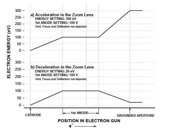
Figure 10. Example of Zoom Lens Acceleration / Deceleration Schematic
The initial elements of this electron gun example all float on the Energy supply; electron energy in this portion of the gun is determined by the potential difference between the cathode and first anode, and as modified by grid and focus. As the electron beam leaves the floating region of the gun and approaches the grounded aperture, it is either accelerated or decelerated, depending on the relative voltage differences between the Energy supply and the 1st Anode supply.
A theoretical schematic energy profile over the length of the gun might be illustrated by Figure 10. For example, if Energy is set to 300 V and 1st Anode is set to 100 V, then the electron beam encounters potentials from -300 V to -200 V to 0 V (relative to ground potential) and attains energies from 0 eV to 100 eV to 300 eV as it passes through the gun. As illustrated in Figure 10(a), the beam is accelerated from 100 eV to 300 eV in the final zoom lens portion of the gun.
Alternatively in Figure 10(b), if Energy is set to 20 V and 1st Anode is set to 100 V, then the electron beam encounters potentials from -20 V to +80 V to 0 V(relative to ground potential) and attains energies from 0 eV to 100 eV to 20 eV as it passes through the gun. The energy profile for this case illustrates that the beam is decelerated from 100 eV to 20 eV in the final zoom lens portion of the gun. If the deceleration ratio (1st Anode to Energy) exceeds 10 to 1, then spot size and beam current may deteriorate.
The deflection elements consist of two pairs (X and Y) of deflection plates located downstream of the focus element. Potentials applied to these plates produce an electrostatic deflecting force in a plane perpendicular to the direction of electron travel, allowing the beam to be aimed or rastered (for units with the Raster Generator option). Deflection allows the beam to be guided by the operator to the target.
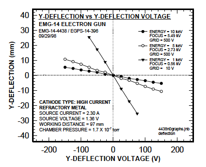
Figure 11. The effect of deflection voltage on the position of the spot a three different energy in a typical electron gun example.
The position of the spot varies directly with the deflection voltages applied (as noted in the Figure 11). However, the amount of movement also depends on beam parameters such as the acceleration energy. At low energies, a given deflecting voltage produces a much larger shift in position. The maximum possible deflection may be less at higher energies than at low energy.
Non-uniformities in the deflecting electric field present at the edges of the deflection plates can cause the spot to become distorted if it is deflected too close to the deflection plates. Distortion varies with both the diameter of the electron beam as it passes through the deflection plate region and the potentials applied to the deflection plates. The greater the diameter of the electron beam as it passes through the deflection plates, the greater the distortion.
Electron beam diameter in the deflection plate region can be minimized by choosing a focus voltage which places the beam crossover between the deflection plates. This however will not minimize spot size at the target.
If a minimum spot size is desired, then a focus voltage must be chosen which places the beam crossover at the target. Under these conditions, the beam diameter as it passes through the deflection plate region is not at a minimum and there will exist more deflection distortion. Better spot shapes will be achieved if the amount of deflection is kept to a minimum.
A magnetic lens typically consists of several electromagnets (essentially coils of wire) placed at the vertices of a polygon in a plane (perpendicular to the axis of the particle beam) to create a customized magnetic field to manipulate the particle beam. For example, four, six and eight electromagnets would create quadrupole, hexapole and octupole magnetic lens systems.
Magnetic beam rocking, which is used in a few high-energy guns, is very similar to rastering. Instead of electrostatic deflection plates, currents in electromagnetic coils around the gun move the electron beam in an unsynchronized pattern over the target area. The effect is the same as rastering, to provide a more uniform coverage of a larger area.
The passing particle is subjected to two vector forces, with one parallel to the core and the other parallel to the lens radius. The magnetic field parallel to the lens radius causes the particle to spiral which then allows the field parallel to the core to influence and focus the electron. The magnetic fields are typically not homogeneous, with particles close to the center less effected than the particles farther away from the beam axis.
Along the beam path there are typically several cross over points. A cross over point is simply a location in the electron beam path where the converged beam reaches a minimum size or cross-section. The brightness or beam current density will typically be greatest at this point. The first cross over point is typically just past the Wehnelt cylinder.
The section below speaks about the temporal control of the particle beam in including methods to turn the beam on and off using the Wehnelt or grid potential along with the various methods available to pulse the beam.
In most guns, the electron or ion beam may be turned off and on while the gun is running. The way this is accomplished depends on the specific gun design; often several methods are available for an electron gun and some of them are discussed below.
The grid, sometimes called G-1 or the Wehnelt, is the first electrostatic element in the gun that the electrons/ions encounter after being emitted from the cathode/ion source. The grid serves as the first control point over the beam and usually can be used to shut off the beam.
In an electron gun, if the grid voltage is sufficiently negative with respect to the cathode, it will suppress the emission of the electrons, first from the edge of the cathode and at higher (more negative) voltages from the entire cathode surface. Please see Figure 7 above for an example of Grid Voltage vs Emission Current.
Similarly, in some ion guns, a positive grid voltage can suppress the positive ions from the ion source. The minimum voltage required to completely shut off the flow of electrons/ions to the target is called the grid cut off. The grid voltage is typically manually controlled by a potentiometer knob on the power supply; thus, in most guns, the beam can be turned off while the gun is running by setting the grid to the “cut off “voltage. Other automated methods to control the grid voltage are covered below.
Pulsing, also called fast beam pulsing, is stopping and starting the flow of electrons or ions in a fast cycle. This pulsing is usually accomplished by rapidly switching the grid voltage to its cut off potential to stop the beam. The gird voltage can be controlled by several different methods (listed in order of speed):
The simplest method of turning the beam off and on is just to cycle the grid voltage by hand with the control knob on the front of the power supply. Clearly, this would be slow and not reproducible.
A more systematic method of controlling the grid is by an input signal into the remote terminals on the rear panel of the power supply. Remote control is a standard feature on all our Kimball Physics power supplies, so this method does not require any system options. However, it may not provide sufficiently fast pulsing.
With the dual grid pulsing option, there are two grid power supplies built into the main power supply. A pulsing TTL (transistor-transistor- logic) signal switches rapidly between the two supplies, pulsing the beam on and off. For most guns, the dual supplies are (1) the normal, variable control grid supply which is adjusted to allow the electron flow and (2) a fixed grid supply which is fixed at the cut-off grid voltage at the factory.
For guns that usually have a positive grid, the dual supplies are (1) a variable positive grid supply which allows the electron flow, and (2) a variable negative grid supply which is adjusted to cut-off.
For the capacitive or fast pulsing option, many guns can be equipped with a capacitor-containing device (either a separate pulse junction box or a cable with a box) that receives signal from an external pulse generator. The grid power supply and pulse generator outputs are superimposed to produce the voltage at the grid aperture. The grid power supply is first set at the cut off voltage. As the grid voltage is negative with respect to the cathode, positive voltage pulses are required to pulse the gun on. The general pattern of the beam pulsing is a square wave with a variable width (time off and time on) and a variable repetition rate. Capacitive pulsing can provide the fastest rise/ fall time and shortest pulse length of the various methods. However, the capacitor does not permit long pulses or DC operation.
Electron guns/sources are often classified by the type of electric field generation (DC or RF), the emission mechanism (thermionic, photoelectron, cold or field emission and plasma source), and by the number of source electrodes. Our discussions will focus on DC field generation, thermionic emission, and single cathode systems.
As previously introduced, the simplest source of electrons in an electron gun cathode could be a metallic wire or filament such as tungsten bent into a hairpin shape, where we apply a small voltage to pass a current through the wire’s resistance to heat the wire. However, most electron emitter configurations used by Kimball Physics indirectly heat the cathode material by thermal conduction from the surrounding support material. The support structure is heated by placing a potential difference (~ 1 – 4 volts) across its resistance, with a “source” current (~1.5 – 3A) heating the conductor.
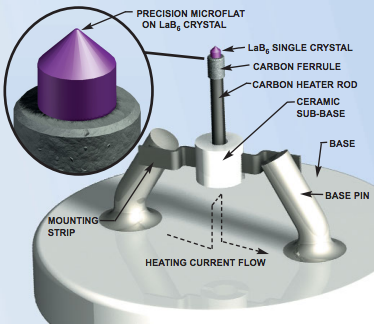
Figure 12. Lanthanum Hexaboride (LaB6) cathode model with heating current path through slotted precision machined single-piece carbon rod and mounting strips with sub-base for rigidity and easier mounting. The diameter of the LaB6 prior to the conic section is about 440 microns. Cone angles are typically 60 or 90 degrees with a microflat at the tip ranging from 6-300 microns.
Kimball Physics emitters provide a reliable source of electrons or ions for use in a variety of instruments including scanning and transmission electron microscopy, electron lithography, x-ray generation, free electron lasers, electron accelerators, and other custom applications. Other applications include our own Kimball Physics electron guns and ion guns.
Cathode types for electron emission available at Kimball Physics include:
Cathodes are available on several types of bases to interface with multiple systems:
Please refer to our cathode documents for more thorough discussions of Kimball Physics various cathode parameters and products.
Also, known as the photoelectric effect, it characterizes the emission of electrons from a material surface when light falls on that object. It involves the transfer of energy from the light to the electron to induce changes in the kinetic energy of the electron.
The energy in the photon to dislodge the electrons must reach or exceed a threshold energy. Below this threshold, no electron will be emitted, even with an increase in light intensity (number of photons per unit time) or exposure time. For example, emission of conduction electrons from typical metals requires a few electron volts (eV), corresponding to short wavelength (high frequency) or ultraviolet light where the photon energy (E = hv) is related to the product of Planck’s constant h and the light frequency (v).
This photoelectric effect can occur in any material. However, as electrons are emitted and a charge imbalance is created, the conductivity of the material determines how much current (electrons) can flow into the material to neutralize the charge imbalance. The energy barrier to photoemission is usually also increased by thin oxide layers on the material surface. Metals with clean surfaces and minimal exposure to oxygen in a vacuum environment are more favorable emitters.
Field emission, also known as field electron emission, is the emission of free electrons induced by a strong electrostatic field. The most common configuration would be from a sharply pointed solid surface into a surrounding high vacuum. Field emission in pure metals requires high electric fields (~1 gigavolt/ meter), high vacuum (~10-10 torr) and are also strongly dependent on the work function of the material.
Applications that would benefit from high brightness electron sources include high resolution microscope and charge neutralization applications (spacecraft). Cold field electron emission usually involves minimal heating of the cathode, with an initial state is internal thermodynamic equilibrium. The geometry of the field emitter tip is typically a sharply pointed wire that enables smaller spot sizes and higher current densities. Methods are also available to thermally assist with field emission and lower the magnitude of the electric field required.
There are three basic processes by which ions are generated in the several Kimball Physics ion guns: electron impact gas ionization, microwave gas ionization, and alkali metal solid surface ionization.
This type of ion source has a filament which emits electrons when heated by the Source power supply. An inert or a reactive gas, such as argon or oxygen, is introduced from an external tank via a gas feedthrough into the region inside the ion gun near the filament. The electrons emitted from the filament are accelerated into the gas region and collide with the neutral gas molecules. If the impact is of sufficient energy, an electron will be removed from the neutral gas molecule, resulting in a positive ion. Usually, the ion will be singly charged. Depending on the energies involved, the primary and the secondary (released) electrons may go on to collide with other gas molecules and cause further ionization. The electrons finally land on a positive structure called the ion cage.
The number of ions produced by electron impact ionization depends mainly on the number of electrons emitted, their energy, the type of gas and the number of gas molecules present to be ionized. The ionization potential of each gas species determines the minimum energy the bombarding electrons must have to remove an outer electron. Within a normal range, the pressure of the gas introduced into the gun is linearly related to the ion beam current produced.
The microwave ion source is similar to the electron impact ion source in that it generates ions from a gas introduced into the gun. However, instead of electron bombardment, it uses microwave power, which is transmitted from an external generator to a helical antenna in the ionization chamber, to heat the gas and create a plasma, a highly- energized state in which the gas molecules are disassociated into ions and free electrons. The plasma can be seen as a glowing gas in the chamber, similar to a fluorescent light tube. After the ions are extracted by several apertures, they pass through an ExB filter that consists of a region with an electrical field (E) perpendicular to a magnetic field (B). This ExB filter separates the ions based on their mass; by varying the electric field, ions of different masses can be selected as in a mass spectrometer. The electrical field is adjusted so that only ions of the type desired (based on their mass) can pass through, while other ions and molecules are deflected. Further lenses control the energy, focus and deflection of the selected ions.
In other ion guns, ions of alkali metals such as Cs+, Li+, or K+, are generated directly by solid surface ionization. Instead of having a filament, this type of ion source has a cartridge containing solid compounds of the alkali metal. When heated by the source voltage, these compounds undergo a solid-solid chemical reaction that releases the alkali metal ions at the surface. These positive ions are then accelerated and focused into a beam as in other guns.
The ions generated by the ion source are then formed into the ion beam. A gun element called the extract aperture, which has a negative voltage relative to the ion energy, accelerates and extracts the positive ions from the region of electron bombardment; this is similar to the function of the anode in the electron gun triode. The grid element, with its potential controlled by the Grid power supply, also helps extract and focus the ions. Depending on the gun, additional elements may be present to accelerate, decelerate, focus and deflect the beam.
Mechanical alignment is available with many gun mounting systems to aid in aiming the electron or ion beam at the target. A rotating flange or a device consisting of two rotating angled disks (a Port Aligner) can be used to mechanically change the position of the gun. Port Aligners are available from several manufacturers.
Many Kimball Physics electron and ion guns have an electrostatic deflection system as an option. In the gun column following the focusing lenses, two pairs of plates (X+, X- and Y+, Y-) are arranged around the path of the beam. Voltages are applied to these plates by manually controlled X and Y power supplies, and the resulting electrical field bends the path of the beam. This deflection is used to move the beam around in the plane of the target to position the beam. In a few guns, magnetic coils are optionally available to similarly deflect the beam for alignment.
Rastering, which is related to deflection, is a continuous movement of the electron or ion beam over the target plane to uniformly cover an area over time. This rastering is similar to what occurs with a TV or CRT screen. Two synchronized, cyclically varying voltages are applied to the X and Y deflection plates in the gun. This causes the beam to move in a synchronized pattern: sweeping back and forth (X direction) while simultaneously moving down more slowly (Y direction), then returning to the start position without sweeping back and forth (retrace). Visually, it appears that the beam covers a large square area, instead of a single small spot. Rastering is occasionally done in an unsynchronized mode.
Magnetic beam rocking, which is used in a few high-energy guns, is very similar to rastering. Instead of electrostatic deflection plates, currents in electromagnetic coils around the gun move the electron beam in an unsynchronized pattern over the target area. The effect is the same as rastering, to provide a more uniform coverage of a larger area.
Because an electron or ion beam is invisible, it must be observed by its effects, by employing some type of detector. Two common types of detectors are phosphor screens, which emit light when struck by the electrons/ions, and Faraday cups, which collect the electrons/ions and allow current measurement. A variety of phosphor screens and Faraday cups available from Kimball Physics.
A grounded phosphor screen in the target position allows visual, real-time observation of the spot produced by the beam. The phosphor screen emits light (photons) when bombarded by high-energy particles, either electrons or ions; the light color, typically blue or green, depends on the phosphor material. On the screen, the electron/ion beam usually appears as a small, solid circle (the spot). If the beam has not been focused, the spot may be much larger, or have fuzzy edges, or be made up of many dots (beamlets), or even (with an LaB6 cathode) have an unusual cross shape. As the position, size and shape of the spot can be easily observed, the screen is useful for alignment and setting the proper operating parameters for the gun.
The use of ion beams with phosphor screens has been challenging in that they often become contaminated quickly with a shortened lifespan. The use of a Microchannel Plate (array of electron multiplier tubes) in front of the phosphor screen seems to help mitigate this problem.
A Faraday cup can be used to detect and measure the actual beam current emitted from the electron/ion gun. The Faraday cup consists of a shielded cup with an aperture, which collects the electrons or ions, and an output wire, which is connected to an ammeter. The Faraday cup can be completely separate from the gun, or it can be part of an assembly mounted to the end of the electron/ion gun and manipulated remotely. Some Faraday cup assemblies include a phosphor screen as well. An array of small Faraday cups or a Faraday cup on mounted on a linear manipulator can be used to measure the distribution of the beam current across the spot; this shows the beam uniformity.
The power supply unit, which is part of the electron or ion gun system, is a complete unit containing electronic circuitry, meters and controls, that takes power input from the outside line and converts it to voltages and currents required to run the electron or ion gun. Individual power supplies within the power supply unit provide the voltage to specific gun elements. The output of a power supply is monitored by either an analog meter (one with a dial and pointer) or with a digital voltage meter (DVM).
These individual supplies can be controlled either manually by the controls on the front of the power supply unit, or remotely by a signal into the remote controls on the rear of the power supply. The manual dial potentiometer controls of the FlexPanel directly controls the output of the individual power supply for the various electron gun elements. By use of the remote-control input terminals, the supplies may be either voltage programmed or resistance programmed. The voltage control signal can be obtained from any source, such as a computer with a digital to analog converter, or an analog supply. Resistance programming involves connecting a resistor to the remote terminals.
In addition to the usual manual or remote control, the source power supply can be controlled in a feedback-regulated mode, labeled ECC for Emission Current Control. In electron guns, this feedback circuitry regulates the source power supply, which heats the filament, so that a constant emission current is maintained from the cathode. Similarly, in alkali metal ion guns, the ECC regulates the heating of the ion cartridge and so maintains a constant ion emission current. In gas ion guns, the ECC feedback circuitry controls the electrons used for ionization, but this does not completely regulate the emission of ions from the ion source, as the ionization is also dependent on the gas pressure and other factors.
Most Kimball Physics electron and ion guns are designed in a mounted configuration, the gun being housed in a tube with a flange for connecting the vacuum system. The mounting system uses a standard type of vacuum flange (a CF or ConFlat flange) that has a knife edge on the sealing surface and comes in standard sizes according to its approximate diameter; for example, a 1.33” CF flange has about 1.33 inch or 34 mm diameter, a 2.75” CF flange (70 mm), and a 6.0” CF (152 mm).
The mounted gun also includes cable connectors for the power supply and vacuum feedthroughs. These are insulated connections for the electrical wires and other tubes needed to connect the gun to the power supply cable and to other external parts, such as a gas tank.
A Kimball Physics Flange Multiplexer, which is used as the mounting system on many electron/ion guns, has a one (2.75” CF) flange surface to connect to a vacuum port and five smaller (1.33”CF) flanges for various feedthroughs and cable connectors.
Some of the simpler guns are also available in an unmounted configuration, which allows the customer to design the housing, mounting system and vacuum connections.
Every new electron or ion gun and power supply, built at Kimball Physics, is individually tested by being run in our vacuum laboratory, with the data on various gun parameters collected. This ensures that each gun functions properly, is well aligned, and meets its specifications. Graphs are provided to the customer showing the results of this testing to aid in determining the operating conditions for the particular gun. Guns returned for rebuild or repair undergo similar, but less extensive, testing. (The only exceptions to this testing procedure are a few simple, firing unit models sold in large batches.)
The data collected depends on the gun model and the needs of the customer. The following graphs are generally included: 1) the V-I Characteristic (Source Current vs Source Voltage), which shows the performance of the particular cathode/ion source; 2) Emission and Beam Current vs Source Current, which shows the overall gun performance, how much beam can be produced, and is used to set the source when running the gun; 3) Emission Current vs Grid Voltage and 4) Beam Current vs Grid Voltage at various Energies, which together show how the grid can be used to improve or to cut off the beam.
Depending on the electron gun, graphs showing focusing parameters, spot size, beam current density, or other properties may also be provided. Additional custom-designed testing procedures can be performed as required by the customer.
Kimball Physics Electron Gun / Beam System Options
Kimball Physics Electron Gun /Beam Systems typically come as a complete system, and include
Several of the features listed below may be included in a pre-configured Tier Level systems or packages for a particular electron gun system. Addition features, depending on the system, may be available as options / add-ons / customizations that can be included in systems for additional cost and include:
Dual Grid Pulsing: This option adds an additional, fixed voltage power supply in series with the variable grid supply which can be activated via an integrated TTL circuit. This option adds a standard BNC connection on the rear panel for TTL signal input. Used to completely cutoff emission from the cathode surface. Not usable simultaneously with emission current control (ECC). Feature requires external pulse generator. TTL pulse width 2us to DC, frequency up to 5 kHz. 500 ns rise/fall time.
*Software generated TTL signal available with appropriate LabVIEW options and hardware
Pulsing, Capacitive: Both variable grid and blanker pulsing can be operated using a capacitive pulse junction box, which combines additively the output from the EGPS and an external high voltage (HV) signal generator. This option allows for shorter pulse width (20 ns to 100 us) with a ~10 ns rise/fall time. Frequency is power and duty cycle limited, see system manual for more details.
*Note: Capacitive Grid Pulsing is standard on all mounted ELG-2 systems*
To LEARN more about pulsing, please visit Beam Pulsing in the Beam Operation section of this document.
Beam Blanking: Adds a copper beam blanking aperture in the optics column before the focus element. Applying a voltage to the aperture shunts the electron beam into a trap, effectively stopping emission from the end of the gun. Voltage is supplied by a variable power supply within the EGPS which can be toggled on/off via TTL input. This option adds a standard BNC connection on the rear panel for TTL signal input. Can be used simultaneously with ECC. Requires external pulse generator. TTL pulse width 1us to DC, frequency up to 5 kHz. 500 n/s rise/fall time.
*Software generated TTL signal available with appropriate LabVIEW options
Beam Blanking, High Current: For systems with both high current and beam blanking options available, the blanking aperture is modified to account for higher current and different electrode geometry. Provides all the same functionality as standard beam blanking.
Adds a second metering circuit to the EGPS for the purpose of higher resolution metering and control with a lower maximum emission value. The circuits can be switched between using a TTL switch embedded in the EGPS unit either through the front panel, software, or the rear panel analog input. The Low range offers a factor of 10 greater resolution at up to 10% the maximum emission current of the High range (e.g., 3.000 mA / 300.0 uA).
Adds a second metering circuit to the EGPS for the purpose of higher resolution metering and control with a lower maximum energy value. The circuits can be switched between using a TTL switch embedded in the EGPS unit either through the front panel, software, or the rear panel analog input. The Low range offers a factor of 10 greater resolution at up to 10% the maximum energy of the High range (e.g., 2000.0 eV / 200.00 eV).
Replaces the standard firing unit in the electron gun system with a higher current firing unit. In the cases of disc emitters, this typically involves increasing the diameter of the emitter surface, though in some cases cathode material may change. Please see option details on each system for more information.
Replaces the standard firing unit in the electron gun system with a firing unit optimized for smaller spots. Generally, this involves replacing the cathode with a precision micro-flat LaB6 cathode, though some systems may differ. Please see option details on each system for more information.
Some gun systems offer multiple cathode material options without significantly changing gun performance. To LEARN more about cathodes, please visit our Cathodes Product Page or visit our Learning Center. Also, please contact Kimball Physics if you need assistance determining which cathode option is best suited to your application.
Raster Generation: Adds the ability to rapidly move the beam along the two deflection axes of the gun system by ramping the voltages or currents of the deflection elements at user set frequencies. User can also set the center and relative amplitude of the raster pattern. Each axis can be adjusted independently. Available through two options:
To LEARN more about rastering, please visit Deflection / Rastering earlier in this document.
Functionally identical to raster generation, though using magnetic deflection instead of electrostatic. Same options apply.
Adds a small faraday cup to the mouth of the electron gun as well as a BNC connector on the mounting flange to read out current. Power input limit 2W. Increases in vacuum clearance requirements.
To LEARN more about Faraday cups, please visit the Faraday Cup Product page or our Learning Center.
Several electrostatic and magnetostatic options are available for defection and focus capabilities, including electrostatic deflection, 2 and 4 pole magnetostatic deflection, two pole magnetostatic deflection and focusing, and four pole magnetostatic deflection and focusing.
For more information about electron beam focus an deflection, please visit the Electron Optics section earlier in this document.
The basic Kimball Physics software package offers all the front panel functionality from a virtual instrument on the user’s computer. System control is executed through simple serial commands. This item must be selected before adding additional software features.
For Electron Guns: The firing unit is the assembly component of the electron gun that emits the electrons; the assembly that can be replaced as a unit, usually consisting of the complete triode (cathode, grid (Wehnelt) and anode) or just the cathode and grid; in some guns, only a part of the firing unit called the firing unit cartridge needs to be replaced.
DR-E – Dual-range Energy (Alternative names: Energy High/Low, Energy High-Low Range)
DR-i – Dual-range Emission (Alternative names: Emission High/Low, Emission High-Low Range)
DR-E/i – Dual-range Energy and Dual-range Emission
Defl – Electrostatic Deflection
Mag Defl (x2) – 2-Pole Magnetostatic Deflection (Alternative names: 2-Pole Magnetic Deflection)
Mag Defl (x4) – 4-Pole Magnetostatic Deflection (Alternative names: 4-Pole Magnetic Deflection)
Mag Defl (x2)/Lens – 2-Pole Magnetostatic Deflection and Magnetostatic Focusing – same connector. (Alternative names: 2-Pole Magnetic Deflection and Magnetic Lens)
Mag Defl (x4)/Lens – 4-Pole Magnetostatic Deflection and Magnetostatic Focusing – same connector. (Alternative names: 4-Pole Magnetic Deflection and Magnetic Lens)
Mag Defl (x2) & Lens – 2-Pole Magnetostatic Deflection and Magnetostatic Focusing (separate connectors)
Mag Defl (x4) & Lens – 4-Pole Magnetostatic Deflection and Magnetostatic Focusing (separate connectors)
Raster – Internal Raster (Alternative names: Internal Rastering; Previous names: Hardware Raster, Hardware Rastering
Note: This option is currently not available due to parts shortages.
GP – Dual-grid Pulsing (Alternative names: Grid Pulsing, Grid Pulser)
BB – Beam Blanking. (Alternative names: Beam Blanker)
HC – High Current
CP – Capacitive Pulsing. (Alternative names: Capacitive Pulsing Capability with Pulse Junction Box)
Demountable – Demountable
Electron Gun (Beam) Systems
Electron Gun (Beam) Systems Product Documents (PDF)
Select PDF Document(s) below:
Low Energy Systems (<5 keV)
| EFG-7 / EGPS-1017 | EFG-7 / EGPS-2017 | EGA-1012 / EGPS-1012 |
| EGL-2022 / EGPS 2022 | ELG-2 / EGPS-1022 | FRA-2X1-2 / EGPS-1011 |
Medium Energy Systems (<30 keV)
| EGG-3101 / EGPS-3101 | EGG-3103 / EGPS-3103 | EGF-3104 / EGPS-3104 |
| EMG-4212 / EGPS-3212 | EMG-4212 / EGPS-4212 | EMG-4215 / EGPS-4215 |
| EGF-4104 / EGPS-4104 | EMG-4210 / EGPS-4210 | EMG-4193 / EGPS-4193 |
High Energy Systems (< 100 keV)
| EGH-6210 / EGPS-6210 | EGH-6002 / EGPS-6002 | EGF-6104 / EGPS-6104 |
| EGF-6115 / EGPS-6115 (Please see EGF-6104) | EGH-8100 / EGPS-8100 | EGH-8105 / EGPS-8105 |
| EGH-8103 / EGPS-8103 | EGH-8201 / EGPS-8201 |
Notes:
Document: KP_Electron_Gun_Systems_Summary_2024_0304
COPYRIGHT KIMBALL PHYSICS 2025, ALL RIGHTS RESERVED